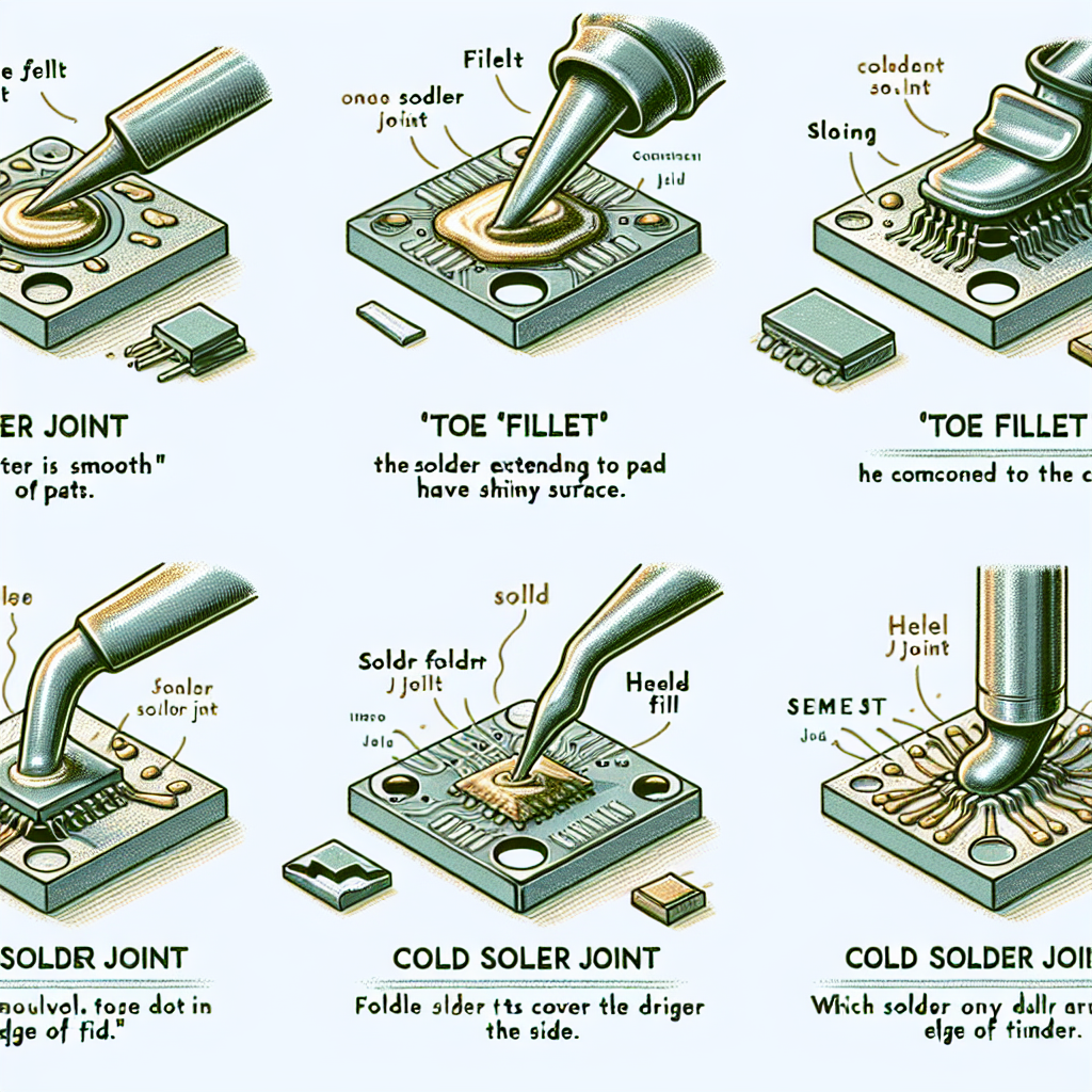
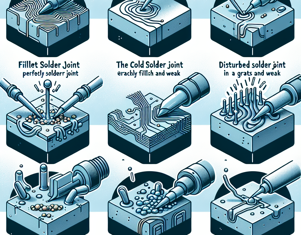
5 Common Types of Solder Joints and How to Create Them
Soldering is a fundamental technique used in electronics and metalworking to join two or more pieces of metal together. It involves melting a filler metal, known as solder, and using it to create a strong bond between the pieces being joined. While the process may seem simple, there are actually different types of solder joints that can be used depending on the application and materials being used. In this article, we will explore five common types of solder joints and how to create them.
1. Lap Joint
The lap joint is one of the most basic types of solder joints and is commonly used in sheet metal work. It involves overlapping two pieces of metal and soldering them together along the seam. This joint is ideal for joining thin sheets of metal and provides a strong bond. To create a lap joint, first clean the surfaces of the metal pieces to be joined. Then, apply flux to the overlapping area and heat the joint with a soldering iron. Once the metal is heated, apply the solder to the seam and allow it to flow between the two pieces, creating a strong bond.
2. Butt Joint
Similar to the lap joint, the butt joint involves joining two pieces of metal together. However, in this case, the two pieces are placed end to end, creating a flush joint. This type of joint is commonly used in plumbing and electrical work. To create a butt joint, first clean the surfaces of the metal pieces and apply flux to the joint. Then, heat the joint with a soldering iron and apply the solder to the seam. It is important to ensure that the solder flows evenly between the two pieces to create a strong bond.
3. T-Joint
As the name suggests, the T-joint is formed when two pieces of metal are joined at a right angle, creating a T-shape. This type of joint is commonly used in structural applications and can provide a strong and stable connection. To create a T-joint, first clean the surfaces of the metal pieces and apply flux to the joint. Then, heat the joint with a soldering iron and apply the solder to the seam. It is important to ensure that the solder flows evenly between the two pieces to create a strong bond.
4. Corner Joint
The corner joint is similar to the T-joint, but instead of joining two pieces at a right angle, it joins them at a 45-degree angle. This type of joint is commonly used in metalworking and carpentry. To create a corner joint, first clean the surfaces of the metal pieces and apply flux to the joint. Then, heat the joint with a soldering iron and apply the solder to the seam. It is important to ensure that the solder flows evenly between the two pieces to create a strong bond.
5. Edge Joint
The edge joint is used to join two pieces of metal along their edges, creating a strong and seamless connection. This type of joint is commonly used in jewelry making and can provide a clean and professional finish. To create an edge joint, first clean the surfaces of the metal pieces and apply flux to the joint. Then, heat the joint with a soldering iron and apply the solder to the seam. It is important to ensure that the solder flows evenly between the two pieces to create a strong bond.
In conclusion, soldering is a versatile technique that can be used to create a variety of strong and durable joints. Whether you are working with sheet metal, plumbing, or jewelry making, understanding the different types of solder joints and how to create them is essential for achieving a successful and professional result. By following the steps outlined in this article, you can confidently create any of these five common types of solder joints for your next project.
Understanding the Differences Between Through-Hole and Surface Mount Soldering

Soldering is a crucial process in the manufacturing of electronic devices. It involves joining two or more metal components together using a molten metal alloy called solder. This process creates a strong and reliable connection between the components, allowing for the flow of electricity and data. However, not all solder joints are created equal. There are two main types of solder joints used in electronic manufacturing: through-hole and surface mount. Understanding the differences between these two types is essential for anyone involved in the production or repair of electronic devices.
Through-hole soldering is the traditional method of creating solder joints. It involves drilling holes in a printed circuit board (PCB) and inserting the leads of electronic components through the holes. The leads are then soldered to the opposite side of the board, creating a strong mechanical and electrical connection. This method has been used for decades and is still widely used in many industries.
One of the main advantages of through-hole soldering is its reliability. The mechanical connection created by the leads passing through the holes provides a strong and durable joint. This is especially important for components that experience a lot of stress, such as switches and connectors. Through-hole soldering also allows for easy replacement of components, as they can be easily removed and replaced without damaging the board.
However, through-hole soldering has its limitations. The drilling process can be time-consuming and expensive, especially for complex PCB designs. It also takes up a significant amount of space on the board, limiting the number of components that can be placed on it. This is where surface mount soldering comes in.
Surface mount soldering, also known as SMT (Surface Mount Technology), is a newer method of creating solder joints. Instead of drilling holes, the components are directly mounted onto the surface of the PCB. This is achieved by applying solder paste to the pads on the board and then placing the components on top. The board is then heated, causing the solder paste to melt and create a strong bond between the components and the board.
One of the main advantages of surface mount soldering is its efficiency. The components can be placed closer together, allowing for smaller and more compact designs. This is especially beneficial for devices such as smartphones and laptops, where space is limited. Surface mount soldering also allows for automated assembly, reducing the time and cost of production.
However, surface mount soldering also has its drawbacks. The joints created are not as mechanically strong as through-hole joints, making them more susceptible to damage from vibrations and shocks. This can be a concern for devices that are exposed to harsh environments. Additionally, the components are not as easily replaceable as through-hole components, as they are soldered directly onto the board.
In recent years, a hybrid method of soldering has emerged, combining the benefits of both through-hole and surface mount soldering. This method, known as mixed technology, involves using both through-hole and surface mount components on the same board. This allows for a balance between reliability and efficiency, making it a popular choice for many electronic manufacturers.
In conclusion, through-hole and surface mount soldering are two different methods of creating solder joints in electronic devices. While through-hole soldering offers reliability and ease of replacement, surface mount soldering provides efficiency and compact designs. The choice between the two methods ultimately depends on the specific requirements of the device being manufactured. However, with the emergence of mixed technology, manufacturers now have the option to combine the benefits of both methods, creating a more versatile and efficient production process.
The Importance of Proper Solder Joint Inspection and How to Identify Defects
Soldering is a crucial process in the manufacturing and assembly of electronic components. It involves joining two or more metal surfaces together using a filler metal, known as solder. The solder is heated to its melting point and then allowed to cool, creating a strong bond between the surfaces. However, not all solder joints are created equal. There are different types of solder joints, each with its own unique characteristics and uses. In this article, we will explore the importance of proper solder joint inspection and how to identify defects.
The first type of solder joint is the through-hole joint. This is the most common type of joint and is used to connect electronic components to a printed circuit board (PCB). The component leads are inserted through holes in the PCB and then soldered on the other side. Through-hole joints are known for their strength and reliability, making them suitable for applications that require high mechanical stress.
Another type of solder joint is the surface mount joint. This type of joint is used to connect surface mount components directly to the surface of the PCB. Unlike through-hole joints, surface mount joints do not require holes to be drilled in the PCB, making the manufacturing process more efficient. Surface mount joints are smaller in size and have a lower profile, making them ideal for compact electronic devices.
The third type of solder joint is the ball grid array (BGA) joint. This type of joint is commonly used in high-density applications where space is limited. BGA joints consist of small solder balls that are attached to the bottom of the component and then reflowed onto the PCB. BGA joints offer excellent electrical and thermal properties, making them suitable for high-speed and high-power applications.
Now that we have discussed the different types of solder joints, let’s delve into the importance of proper solder joint inspection. Solder joints are critical to the functionality and reliability of electronic devices. A faulty solder joint can lead to a malfunctioning device or even a complete failure. Therefore, it is crucial to inspect solder joints to ensure they meet the required standards.
One of the most common defects in solder joints is insufficient solder. This occurs when there is not enough solder to create a strong bond between the surfaces. Insufficient solder can lead to a weak joint that is prone to breaking or cracking. It can also cause electrical issues, such as open circuits or intermittent connections. To identify insufficient solder, inspectors can use a magnifying glass or a microscope to examine the joint closely.
Another common defect is cold solder joints. This occurs when the solder does not properly flow and bond with the surfaces. Cold solder joints are weak and can easily break under stress. They can also cause electrical issues, such as high resistance or short circuits. To identify cold solder joints, inspectors can look for dull or grainy surfaces on the joint.
One of the most critical aspects of solder joint inspection is ensuring that the joint is free from any contaminants. Contaminants such as dirt, oil, or flux residue can prevent the solder from properly bonding with the surfaces, leading to weak joints. Inspectors can use a solvent or a cleaning agent to remove any contaminants before inspecting the joint.
In conclusion, solder joints are an essential part of electronic devices, and it is crucial to understand the different types and their uses. Proper solder joint inspection is vital to ensure the functionality and reliability of electronic devices. Inspectors must be trained to identify common defects such as insufficient solder, cold solder joints, and contaminants. By following proper inspection procedures, manufacturers can ensure that their products meet the required standards and provide reliable performance to their customers.

